by the Profile Design Toolbox:
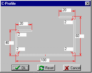
The quickest method for defining a simple profile like U-, C-, Hat- or Z-profile is to use the Profile Design Toolbox (see example on the left: C-profile).
Open the appropriate toolbox window and simply enter the dimensions of the desired profile into the input fields. Further toolbox windows can be used for applying extension segments to the profile (straight and bent elements and combinations of them).

by entering the numerical data:
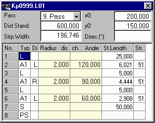
A very quick method for defining a simple profile is to enter the numerical data directly into the profile list. After every input the drawing of the profile is updated. So the correct input can be checked immediately.
The profile list is the numerical description of the profile. Each line of this list describes either a straight segment (L = Line) or a bent segment (A=Arc) of the profile. Entity "PS" terminates the profile list and gives the profile the attribute symmetric; the other half of the profile will be mirrored automatically. Entity "P" splits a profile in two asymmetric halves. After "P" follows the second half.

by CAD drawing:
This is the most comfortable method for defining a profile. It is suited for any kind of profile, especially most complicated ones.
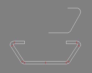
Create a drawing inside of your CAD system. You have to draw the lower contour line only, the sheet thickness is entered later. If you want to design a symmetrical profile, you only need to draw one half (see example in the top). When finished, simply transfer the drawing to PROFIL.